Pages

Showing posts with label Electrodynamics. Show all posts

Monday, February 10, 2025

Pilfered Power

Some time ago I saw an article about the concept of harvesting power from high-voltage transmission lines. The article reported disturbingly large voltages obtained from the equipment they set up, which led them to stop the experiment for the sake of safety (and legal protection). I was curious if I could figure out a way to predict the voltage we could expect from such a situation.

The electric system transmits power with alternating current (AC) at high voltages, which gets stepped-down by transformers when it is delivered to our houses. To see why the transmission is done at high voltage, we can imagine sending out a power P through lines with resistance R:

The power lost is inversely proportional to the square of the voltage, meaning raising the voltage can quickly decrease the power we lose to resistance.

When current travels through a wire, it produces a magnetic field in circles around the wire. The equation for this field is

where μ is the permeability of free space, I is the current in the wire, and ρ is the radial distance from the wire. For alternating current we can write

where I0 is the amplitude of the current and f is the oscillation frequency, 60 Hz in the US. If we set up our fence directly below the transmission line with the z-axis pointing along the fence and the y-axis pointing up toward the wire, then the B-field at this point will be

where h is the height of the transmission wire, and we've replaced I0 with the power & voltage carried by the line. Now to get the voltage induced in the fence, we can use Ampere's Law:

Plugging in our B and integrating to get E gives

Electric field is measured in volts/meter, so this will tell us the relation between the length of our fence and the voltage we can expect between the two ends. The example case discussed in this Wikipedia article uses P = 1000 MW and V = 765 kV. This page gives the minimum height for wires carrying that voltage as 45 ft. Plugging in those values, along with the 60 Hz frequency I mentioned, gives 330 megavolts/meter, which is pretty insane! Now I did assume best (or maybe worst) case numbers in this calculation, but if you watch the video in the article that started this, the presenter seems a bit concerned with the size of the spark he gets at the end. Good (grounded) fences make good neighbors!

Saturday, December 7, 2024

Re: Re: Re: Charge

A topic of much debate when using battery-powered devices, like phones, laptops, or electric toothbrushes is, how often should they be charged? The main schools of thought are, charge whenever you have power available, or charge only when the battery dies or is low. I tend to subscribe to the second theory, on the principle that batteries are typically rated for a fixed number of charge/discharge cycles. My laptop has some built-in protection that limits how often it charges:

Batteries work through a chemical reaction between two reactants suspended in an electrolyte. Electrons pass between the reactants, creating a current and dissolving some of the reactants into the electrolyte. This is a bit oversimplified, but I am, after all a physicist, so that's how I like things. I wanted to see whether this model could back up my charging habits.

The setup I settled on was several electrodes, each surrounded by a block of reactant, and the whole thing surrounded by electrolyte. Then I put the system through several charge/discharge cycles. During each discharge step, we find all the reactant that's in contact with electrolyte, and dissolve it into electrolyte with some probability. During charging steps, we do the reverse: Find electrolyte in contact with either reactant or electrode, and precipitate reactant with some probability. We keep track of how many changes happen each cycle, which corresponds to the amount of current produced, and we vary the number of repeated discharge steps before switching to charging, and vice versa.

There's a lot of parameters to tune here (probability of state change, number of electrodes, amount of electrolyte), so I haven't come close to exploring the full space, but I'm still pretty happy with the results. This case used 200 steps for each discharge/charge cycle:

You can see we use up most of the reactant (yellow) on each cycle. If we switch to only 80 steps, things look a little more ragged:

We can measure how much reactant is around at the start of each discharge, and plot how it changes as we go through cycles for several different cycle lengths:

For all but the extreme 2-step case, these quickly reach an equilibrium max charge (plotted as a fraction of the initial). I was curious what was going on with 2-steps, so I plotted what it looks like at the end of the simulation:

Because of the way I set up the cycling between dissolution and precipitation, the system tends toward holding only as many as it adds on during charging – That's the source of the pattern in the max charge plot above, and not (as I initially thought) my belief about battery health. As result, I think I have to consider this sim inconclusive as far as charging habits. Maybe I'll do a followup later (which will of course be called "Re: Re: Re: Re: Charge")!

Saturday, June 15, 2024

Everything But the Magnetic Sink

I was looking at some of the environmental data supplied by our PUC this week, and I had a thought on the magnetometer reading:

A magnetometer measures the direction and strength of the local magnetic field, similar to a compass. A significant difference though is that a compass only measures the horizontal direction of the field, while this reading shows all 3 dimensions. What's interesting about that is that we can see the field here has a significant z (vertical) component.

The Earth's magnetic field is approximately a dipole, with an offset of 11° from the rotational axis. We can plot the field lines over the surface:

The red line shows the rotational axis, and the magenta line shows the axis of the magnetic field. Notice that the lines come out of the South pole (a source), and go into the North pole (a sink). One of the strange quirks of how we define our magnetic poles is that because the North pole of a compass points toward the North geographic pole, this must be the South pole of the Earth's magnetic field. Using this plot, we can plot the relationship between the vertical angle of the magnetic field relative to the surface and your latitude on Earth:

The two curves represent the two halves of the Earth in the plot above: the right side, closer to the North pole, and the left side opposite it. The PUC gives us the horizontal dotted line, and we can look up our latitude here in Michigan for the vertical line (or "look up" to the North Star if you want to be fancy). In theory, we could measure our longitude by interpolating between the blue and green lines to the point where the red lines cross. Trying that out gives a position of -37.84°, while our true longitude is -83.86°. Maybe I'll stick to using GPS for now!

Sunday, March 17, 2024

Gaussamer Threads

At my lab's group meeting this week, one of my colleagues was showing off the tungsten cube he had purchased to be used in a satellite designed to measure the Earth's mass distribution, similar to the GRACE mission I discussed earlier.

(May contain Infinity Stone)

Since we want the cube to be only affected by gravity, one of the steps in fabrication is degaussing, or removing any residual magnetism. I was curious about this process, since it didn't align with my previous context for degaussing: In high school, I worked for the IT department during the summers, and I was once assigned the task of erasing a collection of video tapes that had been used for a media class. This was done using a degausser, which was essentially an electromagnet that I ran over the surface of the tapes. However, this would put all the magnetic fields pointing in the same direction, not zero them.

One technique I found for driving the field to zero is to apply a large external field, then repeatedly reorient it while decreasing the magnitude. I decided to try this in 2D, similar to the Ising model, but more classical: The magnetic spins can point any direction in the plane, and experience a torque from the surrounding spins and external field. The animation below shows each spin's direction in black, the average direction in red, and the total magnitude of the field as time progresses in the lower plot. The external field is shown on the outer edges.

The way I applied the external fields I think results in the diagonal bias you can see near the end, but overall I'm impressed I was able to reduce the field to 25% of the original value – Not nearly enough for the sensitivity we need though!

Sunday, February 11, 2024

Triboelectric Slide

Recently I've been thinking back to my time at Eaglebrook, which I attended for 7th-9th grade (more on why it's on my mind at a later date). A memory surfaced that seemed ripe for analysis here: I was on the Ultimate Frisbee team, and there was one day that our practice was rained out, so we went to exercise in the hockey rink, which had been drained for the Spring. We decided to play blob tag: In case it's been too long since grade school, any time the person who's It tags someone, they join hands and become a bigger It. By the end of the game, most of the players are joined in one long It chain. We realized that by playing in the hockey rink, we could stretch from one wall to the opposite and simply walk toward the remaining players, who were now cornered. The kids on the ends of the chain ran their fingers along the walls of the rink, and after a few seconds, a massive static discharge traveled down the line from each end, meeting at our coach in the center, who fell to his knees in pain, clutching his arms!

Naturally, thinking of this made me wonder whether I could model the situation. Static electricity is typically caused by the triboelectric effect, in which charges transfer between materials in contact due to differences in the energy states, though the precise mechanism is not fully understood. I decided to try modeling my situation as a circuit:

Made using circuit-diagram.org

Here we have the charged walls providing a voltage (circled arrows) and the players linked to each other (resistor Ts) and the ground (lined triangles). We can analyze this circuit using Kirchhoff's Laws: At each junction of wires, there must be a constant voltage, and all currents in and out must sum to zero. These seem simple, but when you have a tangled mess of components like this, it can get tricky. I worked out what I thought was the answer, doubted myself, worked it out again and got the same thing, so I think this is right. If the static from the wall produces a current I with a voltage V, then the nth person from the wall will discharge a current of

This seems to suggest that the current decreases as we move away from the wall, since the n(n+1) term will grow faster than the n. However, we also need to consider the charge coming from the opposite wall. For N people in the chain, the total will be

Note that we subtract the current from the opposite wall, since it's flowing in the other direction. It's a little hard to see what's going on here, so let's throw some numbers at it: The resistance of skin can vary a lot depending on how dry it is and other factors, but a typical value is 1000 ohms.

For the total current from each wall I, I found a paper on measuring the triboelectric charge transferred for different materials, which happened to include high-density polyethylene (HDPE), the substance commonly used in skating rink walls. Unfortunately, it does not have human skin, but I took their measurement of pigskin as a good representative (and appropriate for the day of the Super Bowl). The numbers they give are charge per area, but we want current, which is charge per time. We can imagine as the players walk forward dragging their fingertips along the wall, the total area will accumulate proportional to the width of the fingers contacting the wall, and the speed they're walking. Using the numbers from the paper, and assuming 1 cm width for each of 4 fingers moving against the wall at 1.5 m/s, we get (30 uC/m^2)*(4 cm)*(1.5 m/s) = 1.8 microamps.

We still need the voltage V, but we know from Kirchhoff's Laws all the individual currents need to sum to I, so we can sum In from 1 to N, set it equal to I, and solve for V:

Now we can plug this into the equation for the current discharge to see what each player gets:

Due to the flip in direction of the current at the far wall, it remains true that the highest current is on the ends, and the person in the center should feel nothing, so already things are looking bad for this model. What about the overall magnitude of the current?

According to OSHA, you start to feel a tingle around 1 milliamp, but below this would not notice anything. Our current is 5x smaller, so certainly not enough to cause the effects I saw (and felt myself)! I think one of the problems with this analysis may be the assumption of continuous discharging – If we let the charge build up for some time before being released, it could generate significantly higher currents, and may not be perfectly symmetric. Perhaps some intrepid Eaglebrook students can repeat the experiment, and gather more data!

Sunday, January 21, 2024

The Fault in Our Ground

Yesterday, we took the camper to refill propane and get it cleaned. When we came back to our site, and plugged in to the campground power, we found nothing was flowing! We tried a couple ideas to solve it, but we were exhausted and it was already dark, so we turned up the (newly filled) propane heat and went to sleep. This morning, after much more troubleshooting, we discovered the issue was the ground fault circuit interrupter (GFCI), which we had tried the previous night, but hadn't performed the necessary reset steps correctly. I thought I'd get some good out of the frustrating experience, and write a post on GFCIs.

Humans are essentially big bags of salty water, which makes us good at conducting electricity. Unfortunately, letting anything more than around 100 milliamps flow through us can be fatal. The 120 volts that the US uses for mains power can create this much current under the right conditions, so we need safety mechanisms to prevent it.

A "ground fault" refers to the amount of outgoing current not matching the amount of current returning to the power source, meaning that charge is finding another path to flow down. We can measure the current in each line using a loop of wire, which picks up the magnetic field of the moving charges and generates a voltage in the loop. If the two lines don't match, we break the circuit:

In this diagram, the green loops measure the current, and the red is the GFCI's circuitry to compare and break the connections. Initially, I had wondered how a single outlet could cut power to all outlets, but this diagram makes that clear: Typically houses are wired with a pair of lines going from the source to some endpoint, and outlets are wired across the two in parallel. However, if we can break these lines immediately after the source, none of the downstream plugs will be powered.

That brings us to our issue: Once the GFCI is tripped, what do you do next? Typically, GFCIs have two buttons on them, Test and Reset. The test button will artificially pop the breakers so you can ensure they work, but critically, this requires having power. Once we had discovered the power wasn't working, we disconnected from the line in case whatever unknown problem was a fire risk. The real issue though was that to reset the GFCI, you need to push those breakers back in. They're designed to stop power within a tenth of a second, so they use powerful springs to open the connection quickly. That means you need to push a tiny button deep inside the outlet with incredible force, something we were incapable of doing last night! Thankfully in the morning we worked it out, and our power is back on without any expensive fix.

Saturday, August 12, 2023

Maximized Magnets

Recently another post from Hack-a-Day caught my eye, discussing a technique for stacking magnets to get a stronger field, called a Halbach Array. You might assume that if you have a bunch of small magnets, the best way to combine them would be stack them with all their poles pointing in the same direction, but it turns out you can get a stronger field by stacking them in an unintuitive pattern:

Wikipedia

The arrows point from south to north pole of each magnet. Using the (wonderfully named) Python package Magpylib we can look at the magnetic field produced by this combination:

The field strength is represented by a higher density of lines, but that's a little hard to read off this plot, so we can also plot the overall magnitude of the field on a line just above and just below the magnets:

Not only is the field stronger than a single magnet's, it's stronger on one side than the other! This gave me pause, since it sounded like a monopole magnet, which is forbidden by Maxwell's Equations, specifically Gauss's Law for Magnets:

This says that for any closed surface S, all the field lines going out of the surface need to be matched with lines coming in, so that the sum cancels. It seems like our setup could have more lines going out the bottom than coming in the top, but the key is that even though the magnitude of the field is stronger on one side of the array, it includes both north and south poles. You can see this in the field plot above: there are lines going in and out on both sides. We can double check by integrating around a box as S:

When the loop closes, we're back to zero, and no laws are violated!

That last section may have been a little technical, so I'd like to end on something (I find) beautiful. In the Wikipedia article for Halbach arrays, they mention a version using magnetic rods, which can be rotated to switch the field from one side to the other. I was curious how the field strength varied during this, so I made an animation with the output from Magpylib:

The dots mark the north pole of each rod. Each 90° rotation swaps the strong side, but I think the movement of the 3 low-field nodes is really cool. Thanks, Hack-a-Day, for introducing me to this nifty structure!

Sunday, April 2, 2023

Ring Around the 'Rora

Recently I started reading a page called Michigan Aurora Chasers, which shares pictures of the aurora taken in our current home state. The pictures are incredible, but I was really interested by a post that came up discussing Newton's Rings, an effect that can sometimes appear when viewing light from a monochromatic source through a series of lenses, like a camera.

Wikipedia has an example of the effect in a microscope, viewing a sodium lamp:

Wikipedia

For aurora viewers, this happens due to using a flat filter over their curved camera lens. When the light passes through the filter, some will bounce between the lens and filter one or more times, changing the phase. This light can then interfere with the light that passed straight through, producing the dark fringes seen above. The extra distance traveled by the light changes depending on how far from the center of the lens it hits:


The wavelength of light also changes how these rings will appear, since the total phase change from bouncing once from each surface is φ = 4πd/λ, where d is the distance between the filter and lens, and λ is the wavelength. We can scan through the visible wavelengths to see how the pattern of fringes changes (thanks to John D. Cook for the wavelength/RGB conversion):
Due to the spherical shape of the lens, as we get farther from the center, the distance changes more rapidly. This means that if we add up several wavelengths (since true monochromatic light is rare in nature), we see that the rings are only visible near the center of the image, as in the aurora photos from the link at the top:

Our area of Michigan is a bit too far south to get to see the aurora in our own sky, so it's been great to get to see the amazing pictures the group members post. On top of that, they introduced me to this really neat optical effect – Thanks Michigan Aurora Chasers!

Saturday, March 20, 2021

Loops on the Ground

This week in one of my group meetings, a colleague presented her work on identifying and eliminating ground loops. I had never heard of the phenomenon, but it's an interesting pitfall in circuit design. When we talk about voltages, we always need some reference point – Voltage isn't an absolute value, but the difference between two points. When designing a circuit, it can be useful (and safer) to have a connection that can give or take current freely. This lets you get rid of excess positive or negative charges, like static electricity, that otherwise could damage components. This is why modern outlets have 3 connections: positive, negative, and ground.

When we connect devices together though, a problem can arise:

Here we have two components, both connected to AC outlets (+, –, GND). One of them sends a signal to the other. Since voltage is a difference, we need a second connection as reference, so we use the ground wire from the outlets. Now we have a loop of wire though – A loop is a type of antenna, which can pick up signals.

According to this article, the voltage produced by a small-loop antenna is

where N is the number of loops (1 in this case), A is the area, λ is the wavelength, E is the electric field strength, and θ is the angle between the loop and the signal. This article, about honeybee exposure to RF signals, gives the maximum electric field strength measured as 0.226 V/m. FM radio signals go up to about 200 MHz, or a wavelength of 1.5 m. If the area of the loop is 0.1 square meters, or about 32 cm per side, we can get as much as 95 mV of interference, easily enough to throw off a delicate measurement!

Marika's parents are visiting us right now, so I asked my engineer father-in-law Scott if he was familiar with ground loops. He related an interesting experience: He used to have a phone that he would plug into his car power, and an audio jack to play music through the speakers. The power and audio shared a ground connection, resulting in a loop that would add static noise on top of anything he played!

Sunday, September 13, 2020

Aunt Enna

We've still been busy moving in here in Florida, hence my long silence. Recently though we've been considering TV options, and I saw an opportunity to tie our search into a post! We'd prefer not to get cable, but we've been missing watching the morning news, and wondered if we could get it over broadcast. As is, our TV won't pick anything up, but the FCC says there should be some channels in our area. That made us consider getting an antenna to help reception.

I had a basic idea of how antennas worked – They transmit and receive electromagnetic waves, and they can be uni-directional, or omni-directional. What I wondered was how they achieve those qualities. It turns out there's a vast number of antenna designs, depending on what type of signal you want, whether you're sending or receiving, and how big it should be.

Before we get into that though, let's go over the principle of an antenna. Radio waves are a form of electromagnetic wave, meaning they consist of an oscillating electric and magnetic field. We want our antenna to translate between those fields and electric current. In the case of long, straight antennas, we use the electric field to do that:

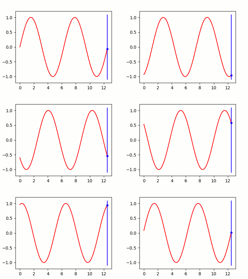
As the electric field (red line) moves through the antenna (blue line) it makes the electrons in the antenna (blue dot) move up and down. This is an alternating current, which corresponds to the signal encoded in the wave.

Those classic rabbit-ear antennas have mostly been replaced by varieties of flat designs, like the one we're considering:

Amazon

I had hoped to get a straight answer on what's inside these, but it seems the designs vary between different models. They appear to be variations on the dipole antenna, which use two wires in opposite directions, but it works on the same principle as the long, straight antennas.

Before I found that teardown page, I was guessing they actually held small loop antennas. These are interesting, because rather than the electric part of the electromagnetic wave, they use the magnetic field to induce current in the loop. That means that the directions they're sensitive in are opposite those of an equivalent electric antenna.

Clearly there's been a lot of study put into designing antennas for different purposes, but with all the other stuff we have on our plate, we're going to try for the cheap one and hope for the best. I'll just be happy if it doesn't explode!

Saturday, November 9, 2019

A Bolt of Cloth

The past couple weeks here have been non-stop drizzling rain – not the nicest farewell I could have – but it reminded me of a post from another of my favorite blogs, Futility Closet.

Wikipedia
Shortly after Benjamin Franklin created the first lightning rod, the idea caught on in Europe as a fashion accessory. There were umbrellas fitted with lightning rods (above), as well as hats, which trailed a wire for grounding. The information on these is a bit sparse, in particular whether they had ever been tested. This concerned me, since I saw some potential problems with the design, which I thought I'd explore today.

First, a quick explanation of how lightning rods work: During thunderstorms, charge collects in clouds. If enough charge builds up, it can overcome the resistance in the air, and create a channel down to the ground, where it discharges. This is lightning, which can carry lots of charge at high speed. Electricity takes the path of least resistance, and since humans and animals carry a lot of salty water, that makes us appealing routes to the ground. Tall buildings can also make good conductors, but since lightning carries so much energy, it can start fires. To protect ourselves, and our homes, we can make even better channels by topping buildings with a metal rod that connects directly to the Earth through a wire. Based on this, the lightning rod apparel doesn't seem unreasonable, but let's look at some issues.

Ground Current
For real lightning rods, the grounding wire is buried several feet deep to better distribute the charge, but that wouldn't be possible with a rod you carry with you. Instead, the wire just drags behind you, but that's no different from lightning striking the ground near you. Lightning carries a lot of charge, and it takes some space to dissipate, which can be just as dangerous as the initial strike. The National Weather Service webpage illustrates this with a charmingly-90s, yet still horrifying, animated GIF:


According to the Washington Post, ground current can be dangerous as far as 60 feet from the initial strike, so you'd need an awfully long tail on your umbrella/hat, not to mention the danger to anyone else who happens to be near the contact point.

Melting Wire
Since these are fashion accessories we're talking about, the Wikipedia article above mentions that the grounding wire was silver, but that could get expensive. One site I found lists the gauge for a grounding wire as 2 AWG, or about a quarter inch. There's also the problem that silver has a lower melting point than copper, 961.78 °C. That made me curious whether you'd be trading electrocution for being sprayed with molten silver.

The energy absorbed by the wire will be
where I is the current, 𝜌 is silver's resistivity, l is the length of the wire, A its area, and t is the duration of the strike. Using those values, along with a normal (rather than rope-sized) silver chain, and a height of 1.8 meters, I come up with 195 Joules, which is nowhere near enough to melt even a thin chain.

Magnetic Field
So at this point, you're still dead from the ground current, but your relatives will be able to salvage your silver chain. What about your smartphone? When current flows through a wire, it produces a magnetic field, according to

I couldn't find info for smartphones, but according to this site, credit cards could be damaged at a distance of 63 centimeters, and pacemakers at 25 meters! I'm not sure whether the short duration of the bolt would change these calculations, but it still doesn't seem like you or your electronics would be safe in a thunderstorm, even if you are wearing the height of 18th century fashion.

Big thanks to Futility Closet for pointing out this fleeting trend! I'm sure we would never use new technology in such a frivolous way, right?

Sunday, November 3, 2019

Riding a Charger

In high school, I got interested in electronics tinkering through the blog Hack-a-Day. I haven't done much myself for many years, but I still read the blog, and last week there was a post that seemed ripe for physics analysis:

The setup is that each player has a button they can press and release. While the button is pushed, a capacitor is charged by a voltage source, and when it's released, the capacitor switches to power a motor that drives the horse. You can see the full plans here, but this is a simplified version of the circuit:
Made using www.circuit-diagram.org
In the state shown above, the voltage source (V) begins to charge the capacitor (C). At first, this would act like a short circuit, so we add a resistor (R) to limit the current flow. For this type of circuit, the charge on the capacitor is given by
The voltage over a capacitor is proportional to the charge stored in it, so as the capacitor charges up, it pushes back more and more on the voltage source, which slows the charge that's added. That leads to an asymptotic behavior:


When the button is released, the switch in the diagram above flips to the other side of the circuit, and the capacitor begins discharging through the motor. This acts like a resistor, but converts the charge flowing through it to motion, driving the horse. Once again, we have an asymptotic relationship, since as the charge flows out of the capacitor, it can't push as strongly:
Here, Q0 is the amount of charge we put on in the first step. This is similar to the plot above, but decaying to zero:


This made me curious if I could come up with the optimal strategy for getting the horse to the end as quickly as possible. That translates into the most charge in the least amount of time, or the maximum current. If we ignore the initial charge up, we can think of switching between some maximum and minimum charge:
The average current through the motor over one cycle is
where tC and tD are the charge and discharge times. The expressions for those are a bit ugly, so I won't write them out here. Rather than try to get the exact maximum current, we can try a variety of values for Qmin/max:
The best option appears to be keeping the capacitor at ~50% charge by rapidly flipping the switch between the two states. As with many games, the answer lies in hyperactivity!

Sunday, February 3, 2019

In Case of Hunger, Induce Cooking


In the apartment here in France, we have a kitchen appliance I've never used before: an induction stove. Growing up, I used the two other kinds of electric stove: resistive hotplates, and halogen lamps. In the first case, current is run through a metal coil, which heats up due to resistance – The electrons bump into the atoms in the coil, transferring energy. Halogen lamps put out infrared light, which is absorbed by whatever is on the stove. Induction cooking takes an entirely different tactic though.

Underneath the glass surface, each element has a coil of wire, similar to the resistive hotplates, but with a different purpose:
By Wdwd - Own work, CC BY-SA 3.0, Link
The resistive hotplates use a coil to spread the energy evenly over the bottom of a pot, but induction cooktops take advantage of Faraday's law:
This says that when an electric field (like the one in a wire carrying current) goes in a circle, it produces a changing magnetic field perpendicular to the surface. Since we use alternating current, the electric field in the stove looks like this:
The left side of the equation quantifies the circular motion you see above. The right side tells us that this motion produces a changing magnetic field coming out of the screen in the plot above.

That magnetic field enters the pot sitting on the stove, and now the relationship is flipped: The changing magnetic field produces an electric field. The pot is a conductor, meaning it has free electrons, which respond to the electric field by accelerating. Just like the resistive hotplate, we now have electrons moving through metal, which results in heat, but this time, it's happening in the pot itself.

By inducing current directly in the pot, we get much finer control over the heat applied – I've been amazed by how quickly things heat and cool on this stove. It's also more efficient than other stoves – Resistive hotplates often have a solid disk enclosing the element to help spread the heat evenly, but this requires more energy to heat up, and that energy is usually wasted after cooking.

The one downside to this method is that the pot needs to be able to absorb that magnetic field efficiently. That means it needs to be ferromagnetic (iron or stainless steel), and it needs to be a certain thickness. Without thinking about that latter requirement, I bought a super-cheap flimsy frying pan, and the stove refused to heat it; the heating cycle only turns on if it senses a compatible pan.

I generally find gas stoves terrifying, since they put out tons of heat, plus explosive/noxious fumes. This induction stove seems like the best of both worlds: fast heating, and low risk!